APML Scanner Test
by Philip Perkins
Scanner: Polaroid
Sprintscan 35 Plus
Serial Numbers: M:602050B (Scanner 1) and L:601151B (Scanner 2)
I had an opportunity to perform the APML test on two separate Sprintscans.
Scanner 1 was the unit loaned to me while my own unit was repaired. Scanner
2 is my own unit after it had been repaired. This unit should have worked fully
to spec - the repair report stated that a full calibration had been performed,
that it had passed all tests, and that the firmware had been upgraded from 5.90
to 5.94. This may be interesting - see the note under non-APML tests. In fact
there were some interesting differences between the two scanners. Superficially
there appears to be very little difference between the two sets of results,
however in most cases very different settings were required in order to achieve
optimum results. These differences are noted under each set of results. The
most significant differences between the two scanners showed up under the non-APML
tests (see below).
As a precaution, the same (new) light tube was fitted to both scanners and
used for all scans in this test, including the non-APML tests, although in practice
I have never recorded any measureable difference in results from the use of
different light tubes.
For a details of other APML Scanner Test results please visit John Blakney's excellent
archive.
|
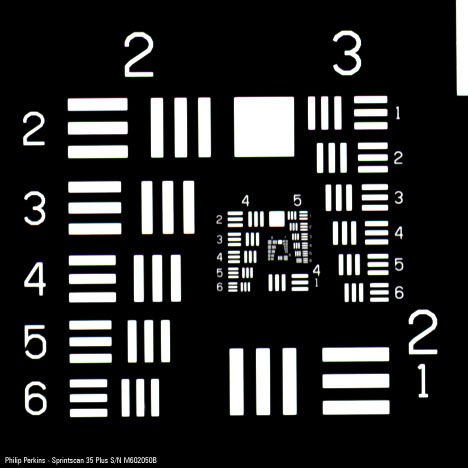
Scanner 1 - S/N M:602050B
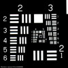
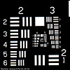
USAF 1951 Target - Greyscale
- Raw Positive Greyscale 2700 dpi 460x460
- Exp: 0
- Sat: 1.00
- Con: 1.52 Br: -40
- Curves: Nil
- Sharpening: +3 Sharpen Detail
- PS: Add ident. layer, save as GIF
|
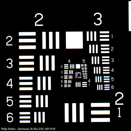
Scanner 2 - S/N L:601151B
USAF 1951 Target - Greyscale
- Raw Positive Greyscale 2700 dpi 460x460
- Exp: -40
- Sat: 1.00
- Con: 1.78 Br: -100
- Curves: Nil
- Sharpening: +3 Sharpen Detail
- PS: Add ident. layer, save as GIF
|
Notes: When I first scanned the Target on Scanner 2 I thought
that the focus must be defective (this may still be the case). Using similar
settings to Scanner 1, the image looked very fuzzy in comparison and the resolution
was well below par. By much experimentation I managed to achieve results that
were essentially the same, however the settings required to achieve this were
very different. Notice the large differences in Exposure, Contrast, and Brightness.
|
Scanner 1 - S/N M:602050B
USAF 1951 Target - Colour
-
Raw Positive Colour 2700 dpi 460x460
-
Exp: 0
-
Sat: 1.00
-
Con: 1.52 Br: -40
-
Curves: Nil
-
Sharpening: +3 Sharpen Detail
- PS: Add ident. layer, save as JPEG
|
Scanner 2 - S/N L:601151B
USAF 1951 Target - Colour
-
Raw Positive Colour 2700 dpi 460x460
-
Exp: -40
-
Sat: 1.00
-
Con: 1.78 Br: -100
-
Curves: Nil
-
Sharpening: +3 Sharpen Detail
- PS: Add ident. layer, save as JPEG
|
Notes: Similar comments apply as to the Greyscale test.
|
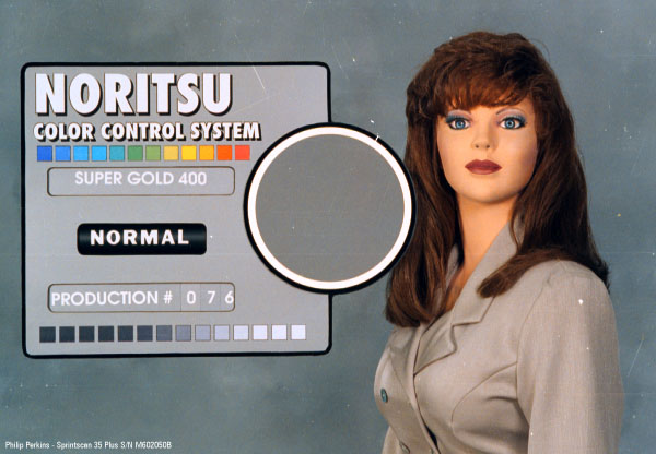
Scanner 1 - S/N M:602050B

Noritsu Test Negative
-
Kodak Ektapress 400 Colour 506 dpi 640x416
-
Exp: T0.00 R0.04 G0.05 B-0.08
-
Sat: 1.00
-
Con: 1.26 Br: -20
-
Curves: Nil
-
Sharpening: 0
- PS: Add ident. layer, save as JPEG
|
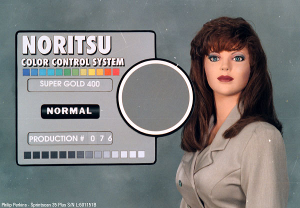
Scanner 2 - S/N L:601151B

Noritsu Test Negative
-
Kodak Ektapress 400 Colour 506 dpi 640x416
-
Exp: T0.04 R-0.02 G0.00 B0.14
-
Sat: 1.00
-
Con: 1.26 Br: -20
-
Curves: Nil
-
Sharpening: 0
- PS: Add ident. layer, save as JPEG
|
Notes: Notice the large increase in blue needed for Scanner 2 in
order to achieve essentially the same result as for Scanner 1. The small colour
difference here may not be due to scanner differences. When I came to do the Scanner
2 scan I found that I could further optimise the accuracy of the scan. I did this
by using the rectangle selection tool to select a square portion of the middle
grey circle. I selected as much of the grey area as possible without cutting into
the white boundary. I then inspected the histogram and made small exposure adjustments
until all three (RGB) histograms were exactly centered on the middle slider. I
believe that the Scanner 2 scan is very accurate, whereas the Scanner 1 scan is
a little less so. This is probably the main factor accounting for the slight colour
difference.
|
Scanner 1 - S/N M:602050B
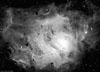
Chuck's M8 - TP 2415
-
BW Negative Greyscale 2700 dpi 1232x888
-
Exp: 0
-
Sat: 1.00
-
Con: 1.00 Br: 5
-
Curves: Large Increase Low, Flat Middle, Decrease High
-
Sharpening: 0
- PS: Add ident. layer, save as JPEG
|
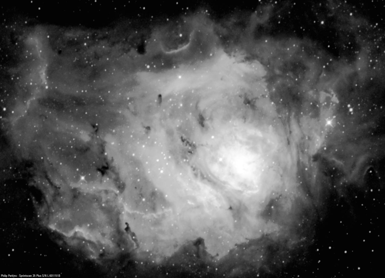
Scanner 2 - S/N L:601151B

Chuck's M8 - TP 2415
-
BW Negative Greyscale 2700 dpi 1232x888
-
Exp: 0
-
Sat: 1.00
-
Con: 1.00 Br: 0
-
Curves: Large Increase Low, Flat Middle, Decrease High
-
Sharpening: 0
- PS: Add ident. layer, save as JPEG
|
Notes: This is the only scan for which I was able to use almost identical
settings for the two scanners. I believe that this is because greyscale scans
are less critical than colour scans - most of the work in scanning involves balancing
the colour channels. For example, the very large curve adjustments which were
made to these scans could not have been made to a colour scan, or the colours
would have appeared very distorted. Close inpsection of the Scanner 2 scan
reveals that it is more fuzzy than the Scanner 1 scan. More on this under the
non-APML tests (below).
|
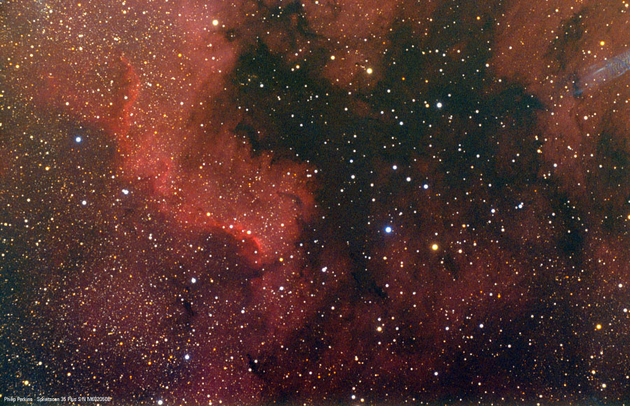
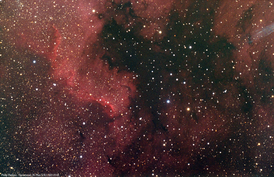
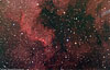
Scanner 1 - S/N M:602050B

Chuck's NGC 7000 - PPF400
-
Kodak Ektapress 400 Colour 675 dpi 900x580
-
Exp: T0.14 R0.06 G0.28 B0.08
-
Sat: 1.08
-
Con: 2.04 Br: -80
-
Curves: Sl Increase Low, Sl Increase Middle, Flat High
-
Sharpening: 0
- PS: Add ident. layer, save as JPEG
|
Scanner 2 - S/N L:601151B
Chuck's NGC 7000 - PPF400
-
Kodak Ektapress 400 Colour 675 dpi 900x580
-
Exp: T0.18 R0.01 G0.25 B0.29
-
Sat: 1.00
-
Con: 2.04 Br: -80
-
Curves: Sl Increase Low, Sl Increase Middle, Flat High
-
Sharpening: 0
- PS: Add ident. layer, save as JPEG
|
Notes: There has been some degradation of the emulsion layers in this negative.
The green layer has become substantially non-uniform. This also affects the blue
layer to a lesser extent. This results in poor appearance of the image when scanned
correctly. A colour difference is visible between these two scans. However in
both cases I set the levels as accurately as possible, so it is possible that
the difference is due to different contrast in the colour channels between the
two scanners. Notice again the very different blue setting required with Scanner
2. Notice also that the Scanner 2 image has a background which looks more blue,
but that the blue stars are less emphasised than in the Scanner 1 image. This
seems strange and I have no explanation, however the difference in blue reponse
between the scanners was very evident when actually doing the scans.
All text and images Copyright © 1997-2022 by Philip
Perkins. All rights reserved.